Thursday, 10 August 2017

Fairing Kit Completed

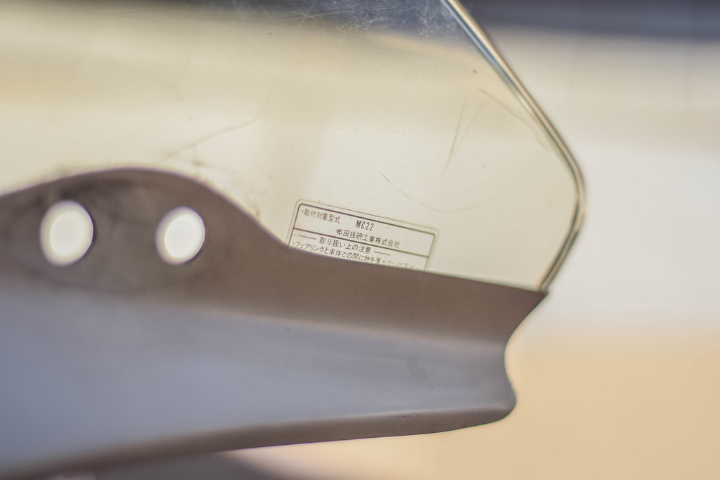
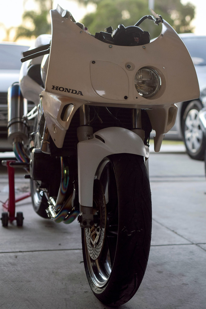
The last pieces of the fairings arrived and the bike could finally get a glimpse at being complete again with a new front cowl, windscreen and front fender. The front cowl is a late 90's endurance FRP cowl, made by SILHOUETTE JAPAN. Very rare to come by in good condition as they are discontinued and can only be found second hand at japanese auctions. An OEM windscreen is to go with the cowl and for the front fender I opted for a cheap FRP TYGA unit as the stock one didn't suit at all.

SILHOUETTE JAPAN front cowl
SILHOUETTE JAPAN front cowl and TYGA front fender fitted
OEM Windscreen

Tuesday, 8 August 2017

Replacement Engine

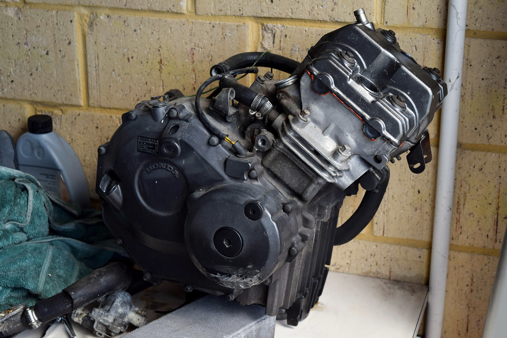
After having issues starting the bike and trouble shooting for about a week, it turns out the engine has really sad compression readings. Double checking the carbureter settings, valves clearances and camshaft positions wasn't a fun time, then I found the ignition leads were badly corroded and replaced those with a spare set (a positive in hindsight) but it was a leak down test that revealed there was more than 80% leakage through the intake valves, which suggests something along the lines of bent valves. Considering it was running (albiet roughly) a year ago I would put it down to my own error at some stage while doing the clearances and not prior damage from the crash. One thing that does come to mind was that the torque wrench used was 1/2 inch and exceeding it's accurate range for the low torque settings on the cam holders.

Head rebuilding for an MC22 engine is more complicated than larger motorcycle engines and fairly costly when compared to buying a second hand engine. Thankfully sourcing a second hand motor wasn't too difficult, picked it up one afternoon and had it in the frame within an hour. These motors are bulletproof and will happily run past the point where the odometer resets but they need a lot of care when touching internals, something that will definitely be kept in mind when it's time to do the valve clearances on this second motor.

Huge thanks to Riley Duddles for providing a second hand engine and Rob Fry for lending his time, knowledge and workshop for a leak down test on the original engine.


Friday, 28 July 2017

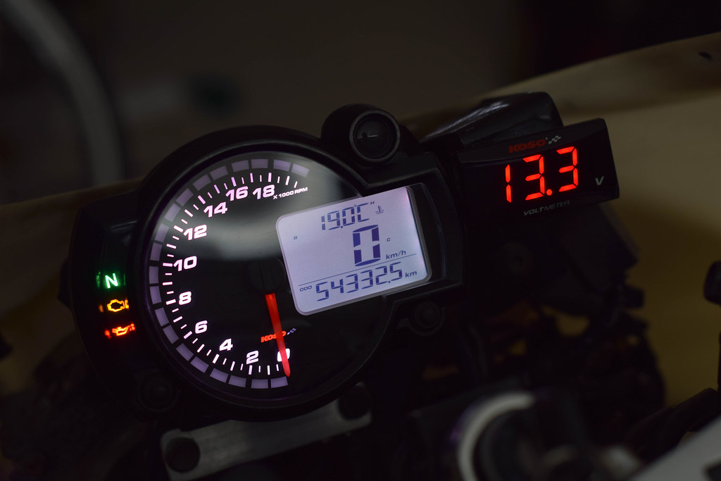
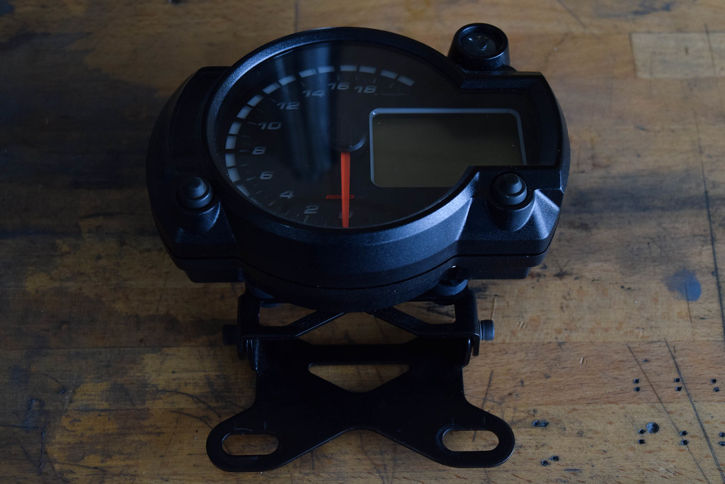
KOSO RX2N+ Meter Installation

The KOSO RX2N+ is a digital race meter and while it does look great it's the functional advantages that make it a worthy replacement over the OEM MC22 dash. It's most useful features in this case are the two temperature displays, magnetic speedometer pickup, shift light, 24 hour clock and warnings like high temperature/high speed readings. Using it allows for the correct speed to be shown with the new sprockets as the magnetic speedo pickup will run off the front wheel rather than a drive off the front sprocket.

In regards to installation it was fairly straight forward, the main harness needs to be wired into the existing MC22 loom with a new positive wire straight from the battery as main power to the meter, the magnetic speedo pickup needs to be mounted off the front forks and the temperature/speed sensors are direct plug and play. There are two issues to highlight though, the first being that the CDI thinks the speed limiter is active when you replace the dash and restricts the engine to 8,000RPM; this was fixed by shorting two wires from the CDI. The second is that using the MC22's RPM signal wire causes reading issues at low RPM due to EMI in the loom, so routing a shielded wire from one of the coil packs was necessary.


☆PROCESS☆

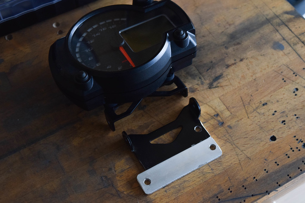
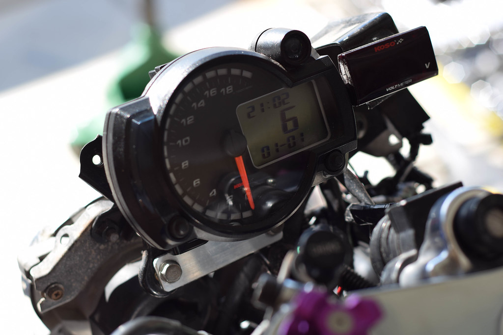
The first step is mounting the KOSO unit itself to the MC22's fairing stay. It will mount up fine using the bracket provided with an extra bolt/washer but due to clearance with the new cowl and windscreen it needed to be modified.
.

Cutting the KOSO bracket down and drilling a new hole for the thread on the MC22's fairing stay provided the top clearance for the windscreen. From there a second bracket was made from aluminium flatbar allowing it to be securely fixed without any modification to the fairing stay.


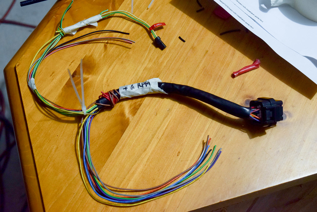
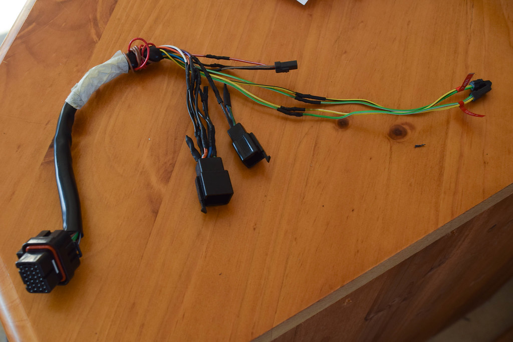
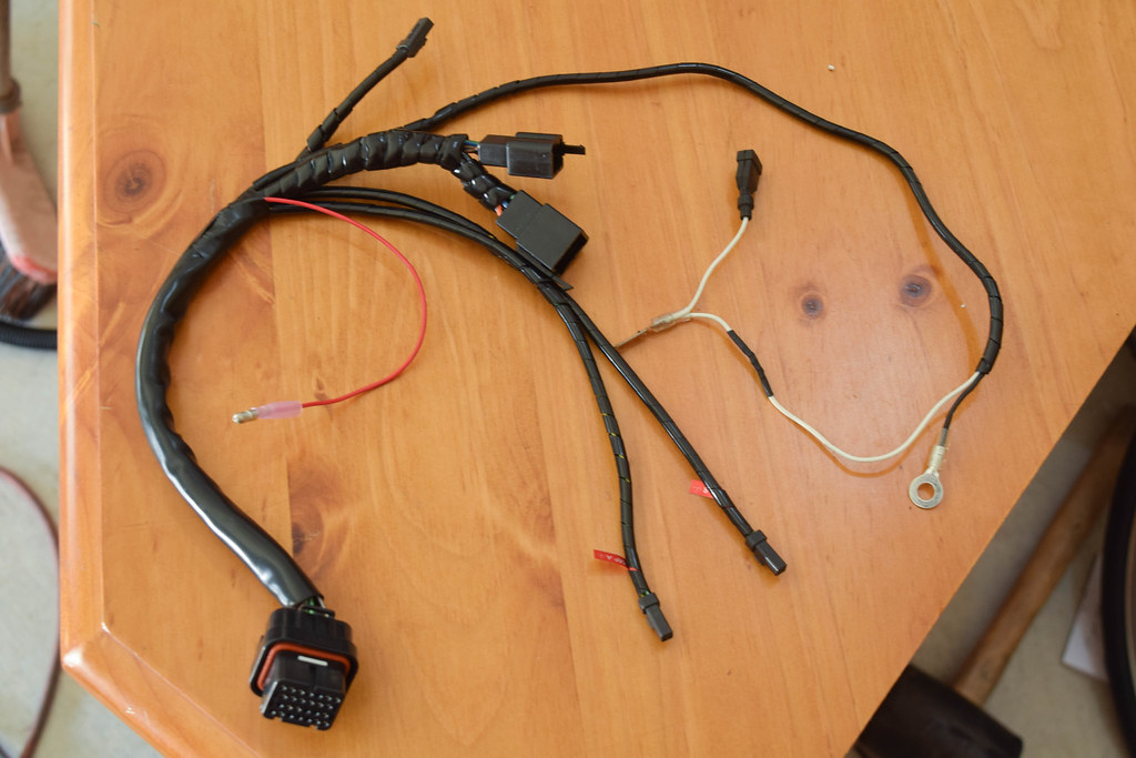
The next stage is wiring the KOSO's harness into the MC22's wiring loom and the easiest way to do that is to cut the connectors off the old MC22 dash and wire those to the KOSO harness; keeping it neat and plug & play. The harness is much longer than needed so trimming that down and mocking up the wire routing was the first priority.


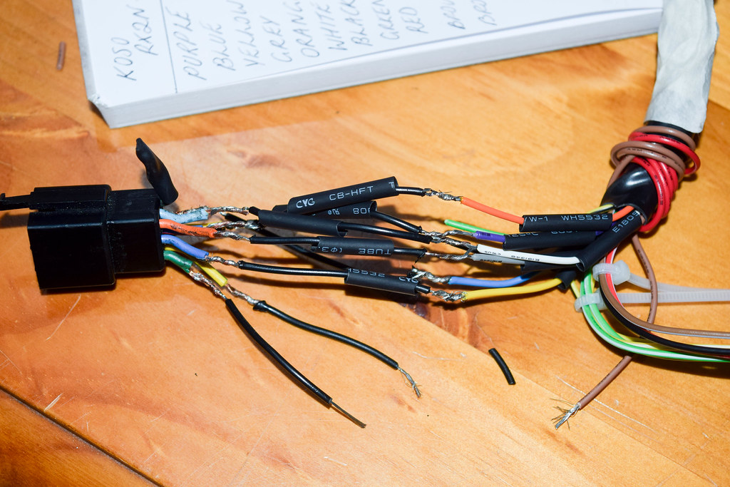
Soldering the wiring together and heat shrinking is always the best option, rather than using the crimp on connections included in the kit.

The wiring connections are listed below along with their purpose.

KOSO -> MC22

Black -> Green        ☆ Purpose: Earth
Blue -> Light Green w/ Red Stripe        ☆ Purpose: Neutral Light
Brown (With Connector) -> +Side Ignition Coil Pack        ☆ Purpose: RPM Signal
Brown -> Brown        ☆ Purpose: 12V Ignition (Key on)
Green -> N/A         ☆ Purpose: Fuel Signal
Grey -> Orange        ☆ Purpose: Left Turn Signal
Orange -> Dark Blue w/ Red Stripe        ☆ Purpose: Oil Pressure Light
Red -> 12V+ Battery        ☆ Purpose: 12V Main Power (Constant)
Violet -> Black/Yellow        ☆ Purpose: EOBD Light (Side Stand Indicator)
White -> Light Blue        ☆ Purpose: Right Turn Signal
Yellow -> Blue        ☆ Purpose: High Beam Light


The last two wires left were the RPM signal and direct 12v feed, for the direct 12v a bullet style connector was used and the RPM signal wire was modified from the shielded cable provided in the kit. 


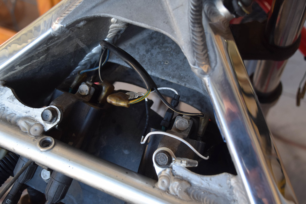
To help eliminate any possible EMI the RPM signal wire runs along the front fairing stay, through the front triple and under the frame to the right side ignition coil.


One of the two temperature sensors simply replaces the existing factory sensor on the thermostat behind the carburetors.


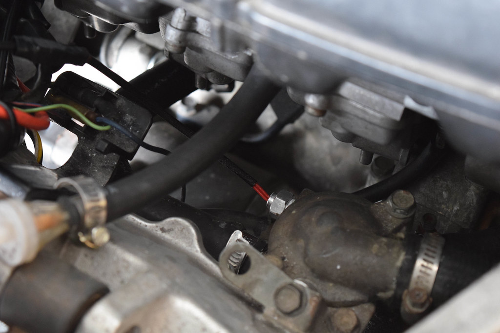
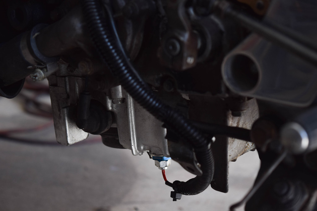
The MC22 doesn't come factory with any engine temperature sensor or fitting for one apart from the oil pressure sensor, but that's far more important than knowing the temperature of the oil. Two options came to mind, either drill and tap the sump or use an adapter where the sump drain plug sits. Due to not having a tap and die set at my disposal I chose the latter, and with a M14X1.5 to 1/8NPT adapter the sensor can be mounted from the sump. The downside is that it will make future oil changes less convenient. 


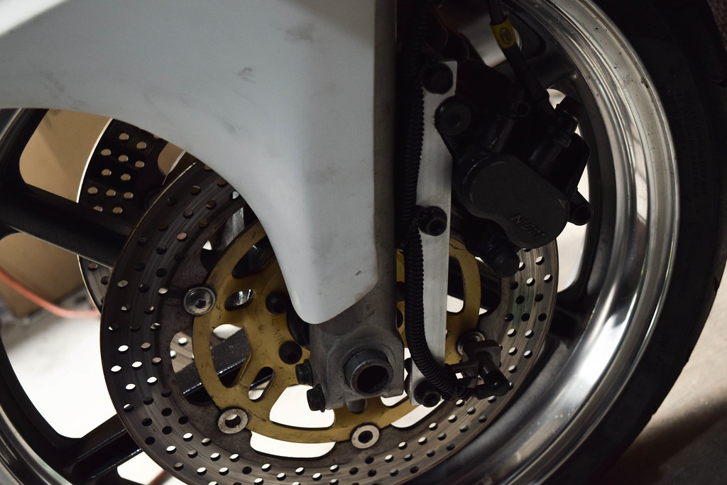
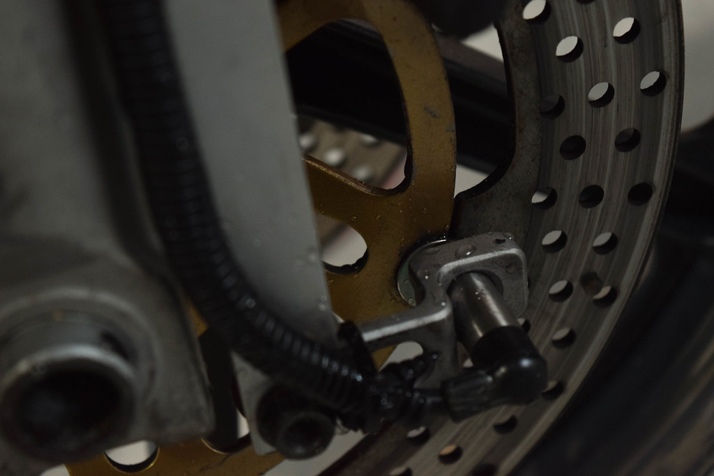
The magnetic speedometer pickup works by sensing points on the brake rotor and calculating the speed based off the rate in which they pass the sensor. After trial and error the best result was to use the buttons on the brake disc and original MC22 fairing bolts with lock nuts, two spaced opposite from eachother. More sensor points on the brake rotor mean a more fluid reading but it also throws the balance of the wheel off if too many are added.


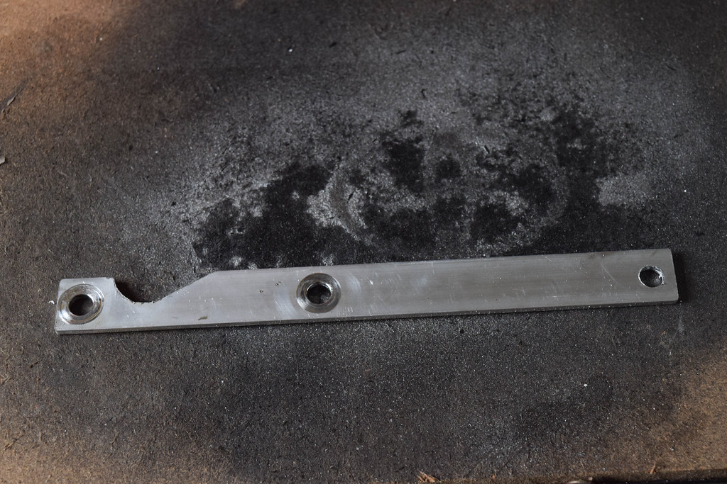
To mount the sensor a bracket cut from aluminium flatbar was made to fit infront of the left side caliper.


The sensor needs to be within 2mm or less from the sensor point to get the best performance.


The last step of the installation before powering on the unit and configuring the settings was to cut the Orange/Blue wire from the CDI and splice it into the Black/White wire. This deactivates the speed limiter.

As a reference point for settings, 2 sensor points and 1810mm for the wheel circumference in the speed sensor setting and HiAct and 1 (4C-2P) in the RPM input pulse setting.
Sunday, 2 July 2017

MotoGear.jp Full Titanium 4-1 Exhaust

This is one of the few parts that have been stored away for almost a year and a half, waiting for the rebuild of the bike. It's a full titanium 4 into 1 system made by MotoGear in Japan. Having previously purchased a slip-on muffler from them for the standard MC22 system the temptation to get a full system was always there, and besides price there is really no downside as the build quality of their exhausts are second to none. The whole system only weighs in at 3.2kg, basically half the stock system and rated at 98 decibels without the baffle.


At the current time the rough settings for the carburetors to suit the exhaust are as follows:

Main jets:
(1)  -  (2)  -  (3)  -  (4)
118 - 115  - 115  - 118

Stacks OEM
Needles OEM
Airbox OEM
Mixture screws 2 turns out


Friday, 2 June 2017

Wheel refurbishing

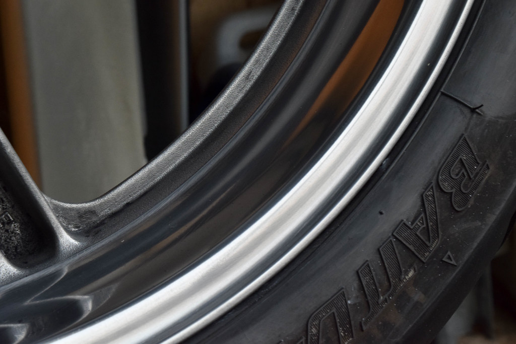
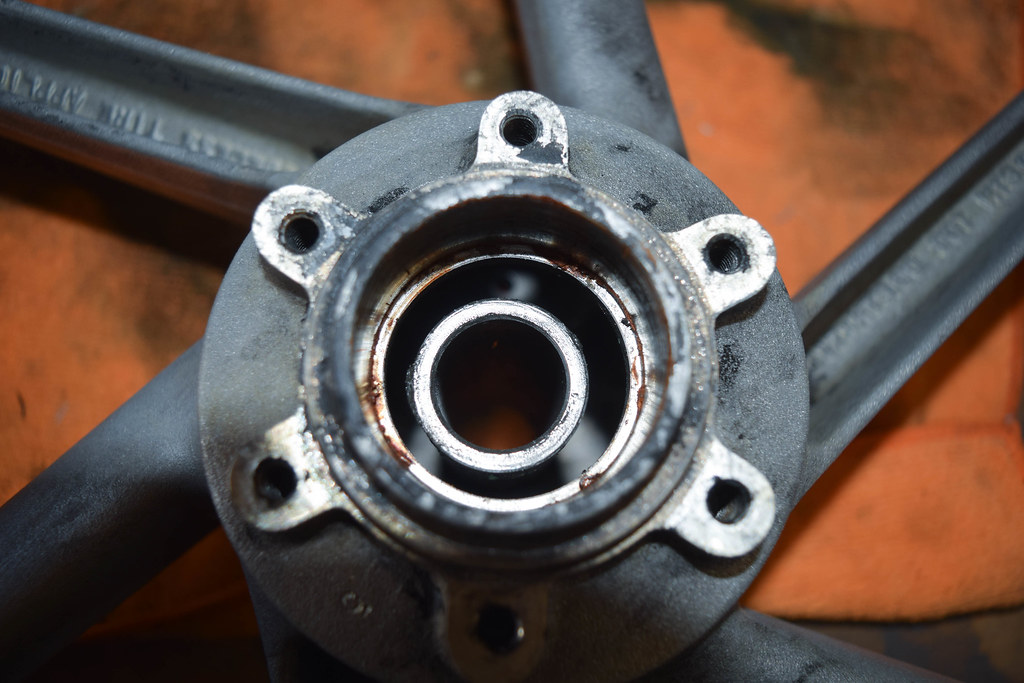
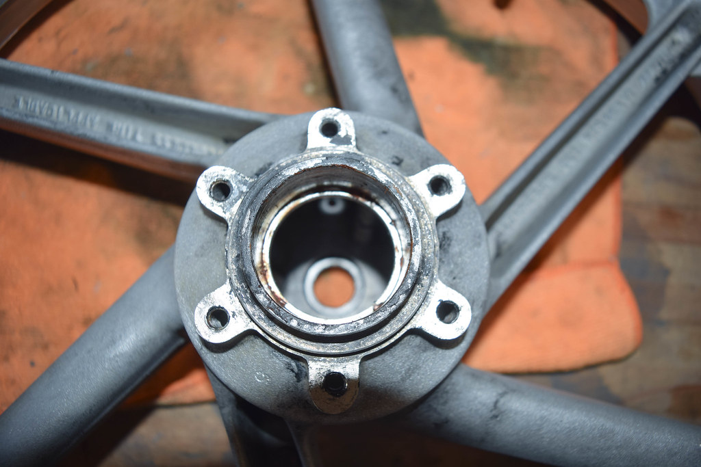
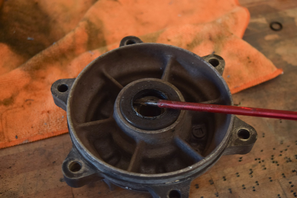
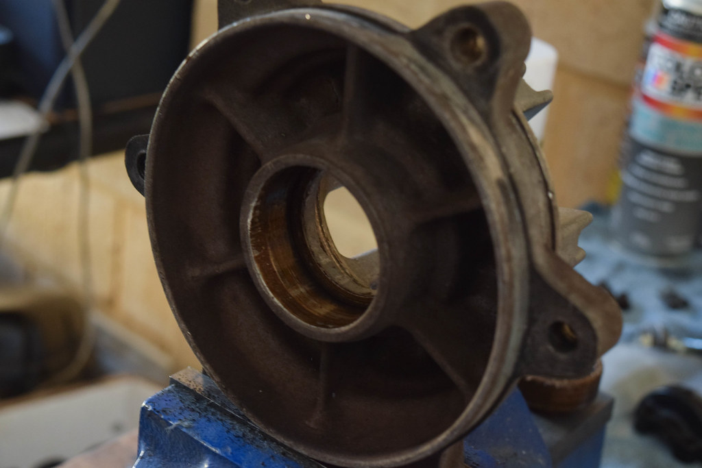
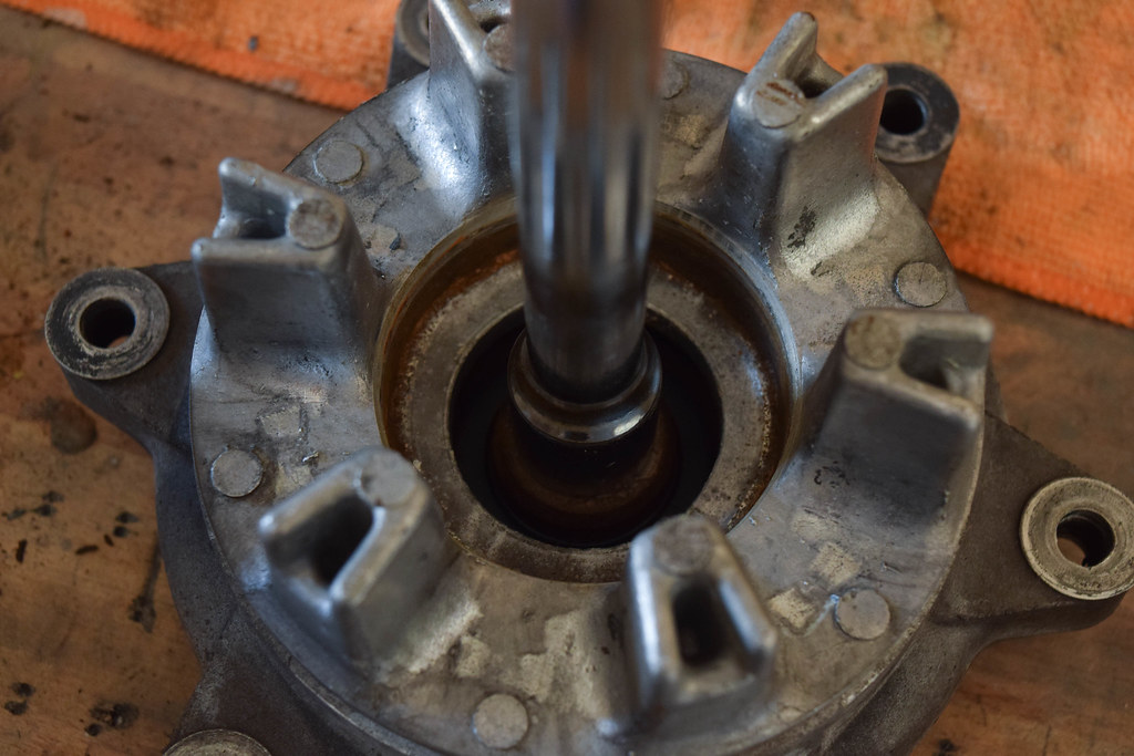
The original idea for the wheels was to just paint them and be done with it, but after gaining some more appreciation for polishing I decided to go with chrome lips and charcoal faces. The wheels were stripped back to bare metal and had their bearings removed. Once there the lips were sanded and buffed, before painting the faces charcoal grey and installing new bearings. Unfortunately I had some bad luck, having to polish the wheels twice as a tyre fitter damaged the lips on both wheels while fitting spare tyres. Funnily enough it's the first time a workshop has touched anything on the bike since the build started. Once the wheels were out of the way the sprocket carrier was repainted and fitted with a new bearing, dust seal and a hefty 53 tooth 520 pitch sprocket.


☆PROCESS☆

POLISHING


To prepare the wheels for sanding they were covered in diggers paint stripper (applied with a brush) to get them back to bare metal. It takes about 3-4 heavy coats to do a good job. 

Paint on wheels bubbling due to paint stripper
Wheels stripped back to bare metal
From there the actual sanding started, the items used were (in order):

  1. Grinder Poly Flap Disc 'Fine' 
  2. P600 Grit Wet
  3. P800 Grit Wet
  4. P1200 Grit Wet
  5. Sisal Wheel w/ Tripoli Compound
  6. Loose Leaf Wheel w/ SS Compound
  7. Loose Leaf Wheel w/ 'PURPLE' Metal Polish

Grinder Poly Flap Disc 'Fine'
P600 Grit Wet
P1200 Grit Wet
Loose Leaf w/ 'PURPLE' Metal Polish

The lips came up great however they aren't a proper mirror finish like the frame, finer sanding before the buffing stage would give them the same finish.


BEARINGS

1. REMOVAL

(FRONT/REAR WHEEL)

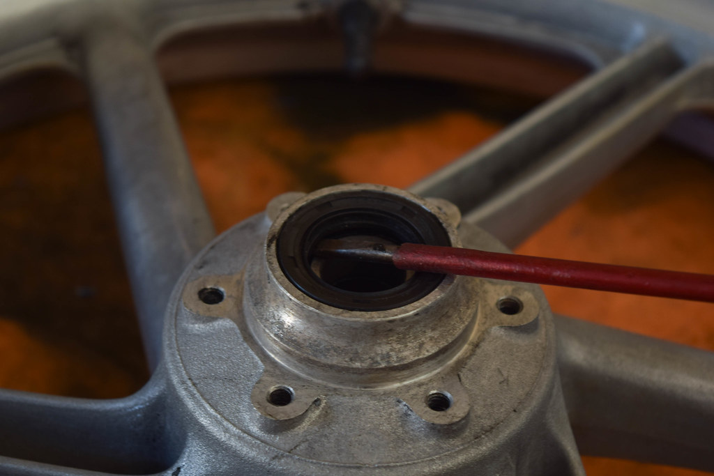
Firstly the dust seals need to be removed by prying upwards from underneath with a flat head screw driver.
Flat head screw driver positioned under the dust seal


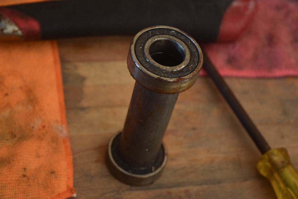
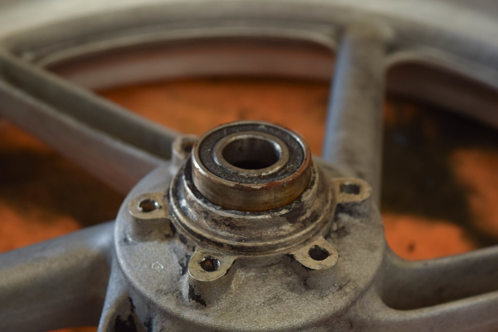
Besides the wheel, the assembly that the axle sits in includes the dust seals, bearings and a metal collar. The bearings are placed on either side of the wheel with a metal collar between them which the axle sits inside. The only difference between the front and rear is that there is no dust seal on the sprocket carrier side (assuming it's not attached).

Bearings either side of metal collar
In order to remove the bearings a flat head screw driver and a hammer both need to be used to catch the inner lip of the bearing and force it outwards. As the bearing moves outwards the metal collar becomes free and more of the bearing is revealed making it easier to force out.

Bearing almost fully removed
Bearing removed and metal collar revealed
Bearings and metal collar all removed
Both front and rear wheels run this design/setup.


(SPROCKET CARRIER)


Again, the dust seal needs to be removed by prying upwards from underneath with a flat head screw driver.

Flat head screw driver positioned under the dust seal

A 1/2" ratchet extension fits the inside of the bearing perfectly and works well with a hammer to drive the bearing out of the sprocket carrier.

1/2" ratchet extension positioned on bearing ready to drive it out of sprocket carrier
Sprocket carrier bearing removed
It's important to be mindful of the collar that sits inside the bearing, as that needs to be transferred to the new bearing on reassembly. With the collar hanging free and the bearing held by two surfaces a flat head will lightly tap the collar out. 

Flat head screw driver used to push the collar out of the bearing
Collar removed from sprocket carrier bearing


2. INSTALL

(FRONT/REAR WHEEL)


Installing new bearings is just as straight forward. Important notes are to keep the bearings in a freezer before the install to help ease them into place and, to only apply force to the outer metal ring on the bearings when hammering them back into the wheels to avoid damage (large sockets are good to use for this).

Bearings in freezer
Bearing ready to be hammered in
Large socket used to hammer in the bearing evenly
Bearing in correct placement
Showing alignment between bearings and collar
The dust seals are then reinstalled/replaced.

The rear wheel is the same setup again.
.
Rear wheel, bearings and collar installed


(SPROCKET CARRIER)

The metal collar that was removed from the old carrier bearing needs to be pressed/hammered into the new bearing before reinstalling (it can also be done afterwards but will shift bearing position). Again, a socket is used to press the bearing into the sprocket carrier.

Bearing with collar installed
Dust seal installed