In regards to installation it was fairly straight forward, the main harness needs to be wired into the existing MC22 loom with a new positive wire straight from the battery as main power to the meter, the magnetic speedo pickup needs to be mounted off the front forks and the temperature/speed sensors are direct plug and play. There are two issues to highlight though, the first being that the CDI thinks the speed limiter is active when you replace the dash and restricts the engine to 8,000RPM; this was fixed by shorting two wires from the CDI. The second is that using the MC22's RPM signal wire causes reading issues at low RPM due to EMI in the loom, so routing a shielded wire from one of the coil packs was necessary.
☆PROCESS☆
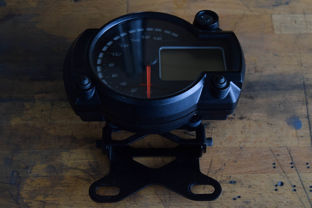
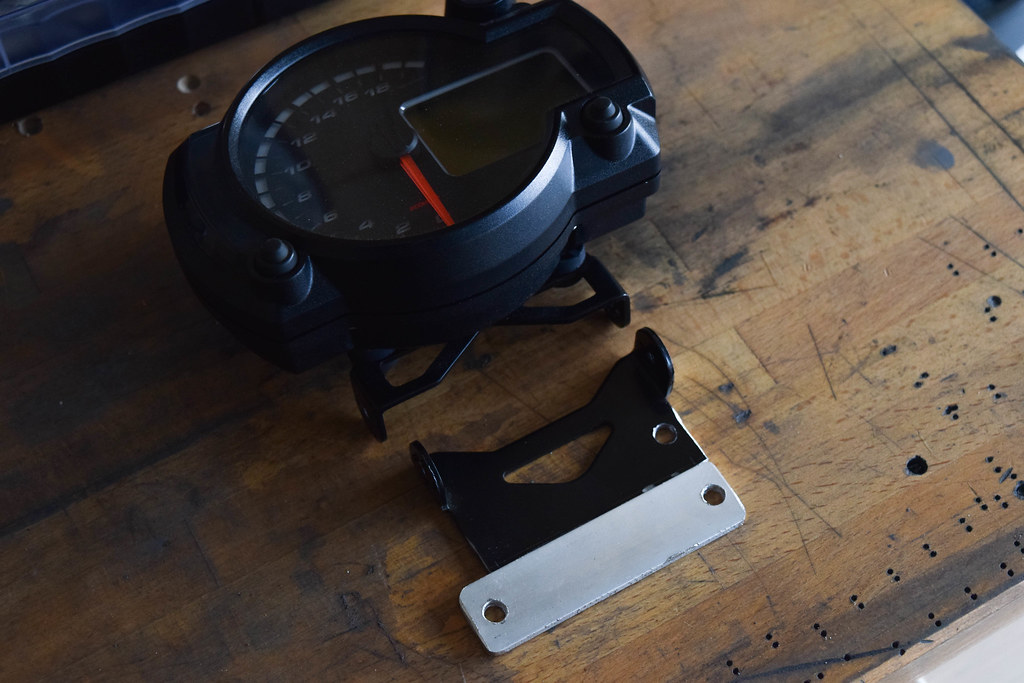
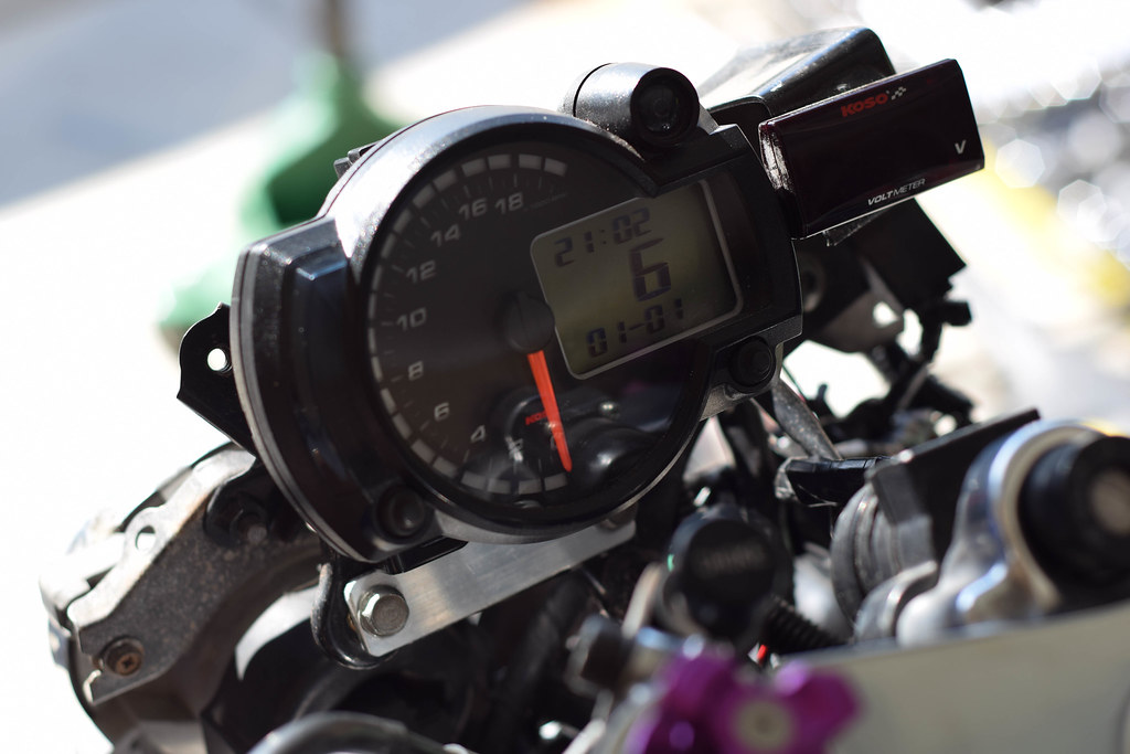
The first step is mounting the KOSO unit itself to the MC22's fairing stay. It will mount up fine using the bracket provided with an extra bolt/washer but due to clearance with the new cowl and windscreen it needed to be modified.
.
.
Cutting the KOSO bracket down and drilling a new hole for the thread on the MC22's fairing stay provided the top clearance for the windscreen. From there a second bracket was made from aluminium flatbar allowing it to be securely fixed without any modification to the fairing stay.
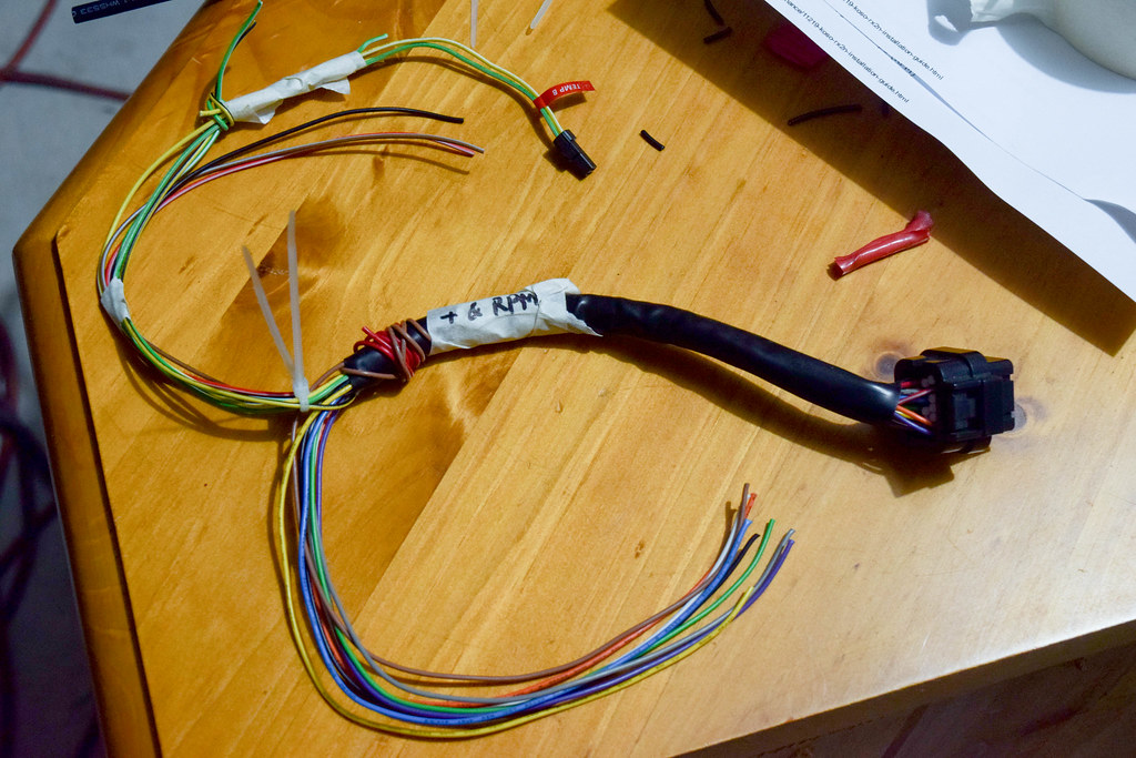
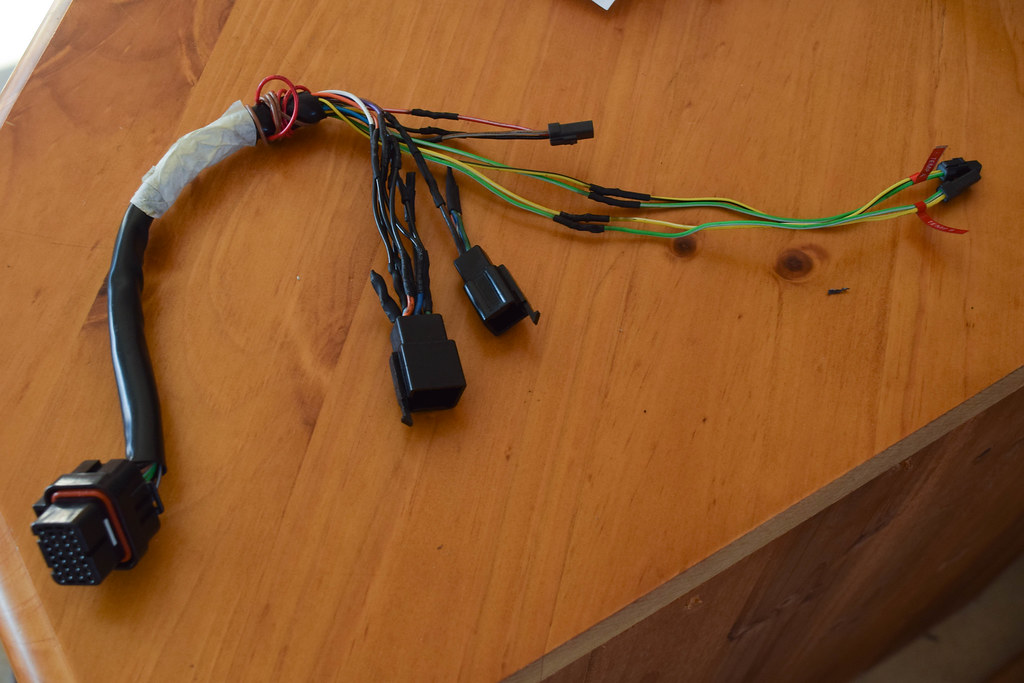
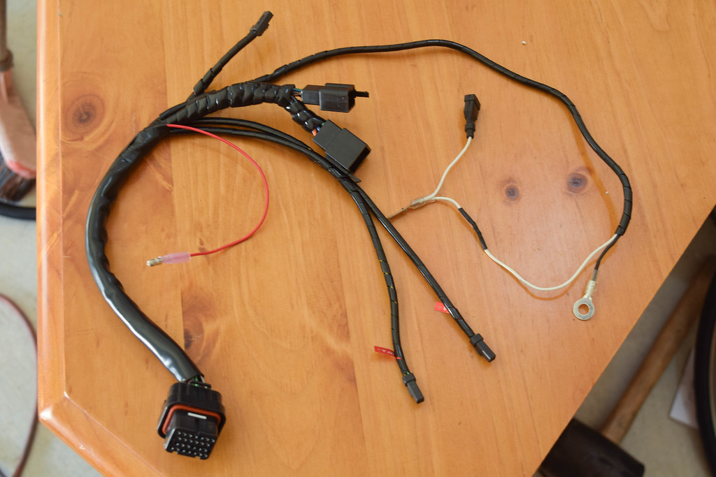
The next stage is wiring the KOSO's harness into the MC22's wiring loom and the easiest way to do that is to cut the connectors off the old MC22 dash and wire those to the KOSO harness; keeping it neat and plug & play. The harness is much longer than needed so trimming that down and mocking up the wire routing was the first priority.
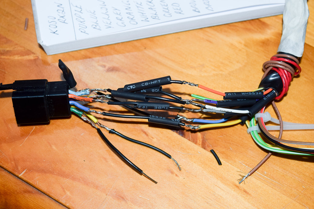
Soldering the wiring together and heat shrinking is always the best option, rather than using the crimp on connections included in the kit.
The wiring connections are listed below along with their purpose.
KOSO -> MC22
Black -> Green ☆ Purpose: Earth
Blue -> Light Green w/ Red Stripe ☆ Purpose: Neutral Light
Brown (With Connector) -> +Side Ignition Coil Pack ☆ Purpose: RPM Signal
Brown -> Brown ☆ Purpose: 12V Ignition (Key on)
Green -> N/A ☆ Purpose: Fuel Signal
Grey -> Orange ☆ Purpose: Left Turn Signal
Orange -> Dark Blue w/ Red Stripe ☆ Purpose: Oil Pressure Light
Red -> 12V+ Battery ☆ Purpose: 12V Main Power (Constant)
Violet -> Black/Yellow ☆ Purpose: EOBD Light (Side Stand Indicator)
White -> Light Blue ☆ Purpose: Right Turn Signal
Yellow -> Blue ☆ Purpose: High Beam Light
The last two wires left were the RPM signal and direct 12v feed, for the direct 12v a bullet style connector was used and the RPM signal wire was modified from the shielded cable provided in the kit.
To help eliminate any possible EMI the RPM signal wire runs along the front fairing stay, through the front triple and under the frame to the right side ignition coil.
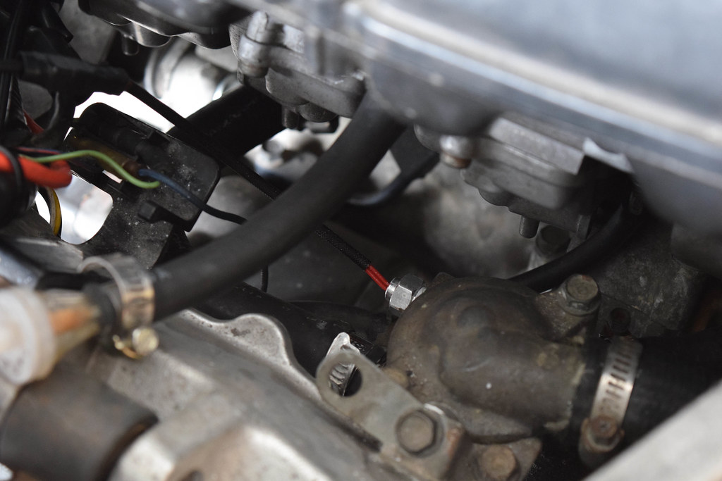
One of the two temperature sensors simply replaces the existing factory sensor on the thermostat behind the carburetors.
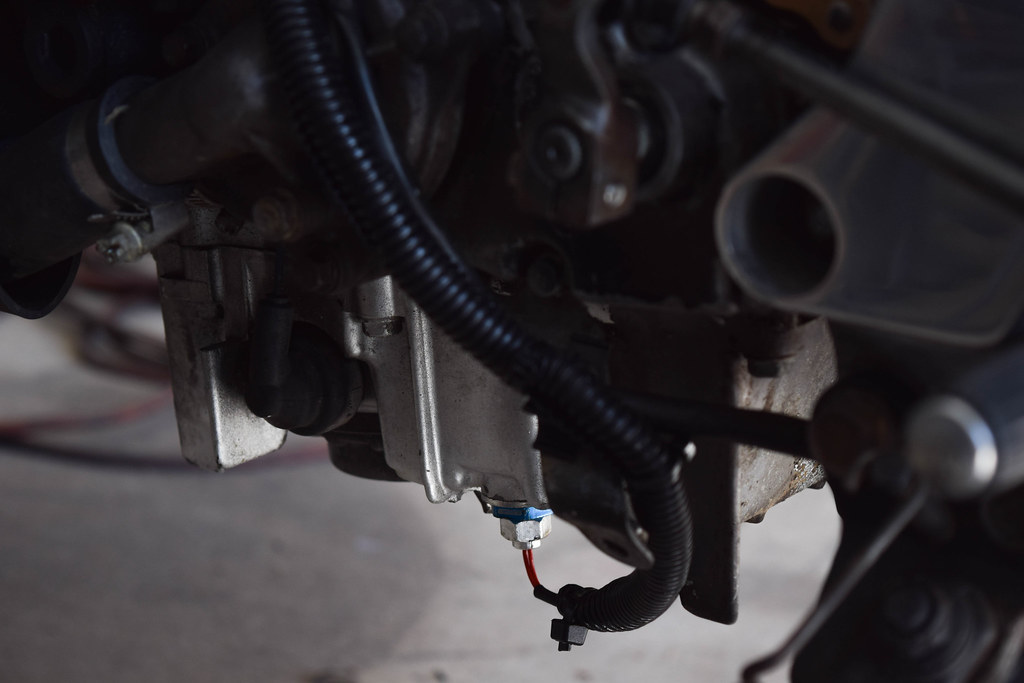
The MC22 doesn't come factory with any engine temperature sensor or fitting for one apart from the oil pressure sensor, but that's far more important than knowing the temperature of the oil. Two options came to mind, either drill and tap the sump or use an adapter where the sump drain plug sits. Due to not having a tap and die set at my disposal I chose the latter, and with a M14X1.5 to 1/8NPT adapter the sensor can be mounted from the sump. The downside is that it will make future oil changes less convenient.
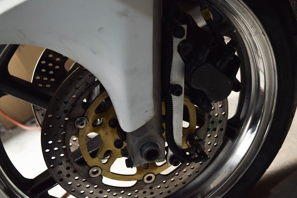
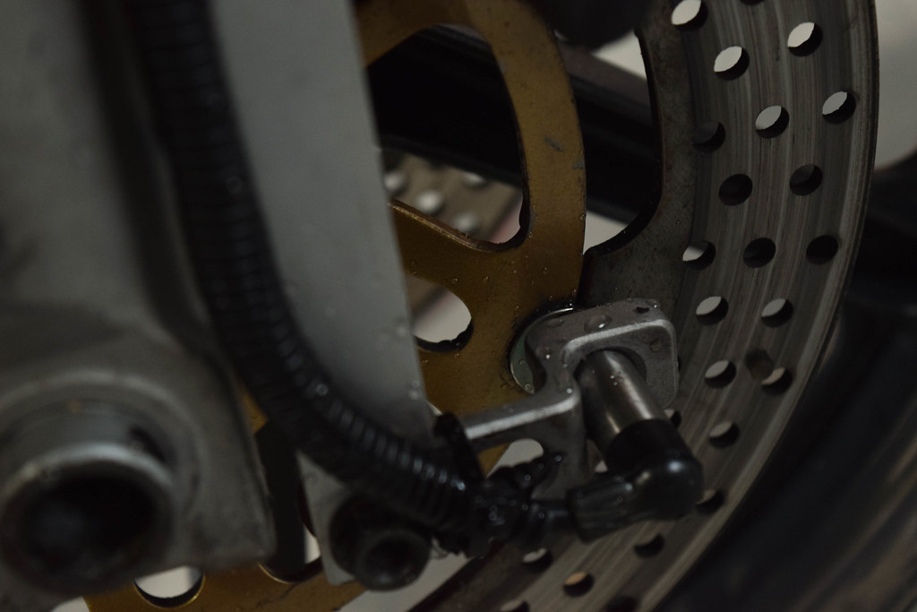
The magnetic speedometer pickup works by sensing points on the brake rotor and calculating the speed based off the rate in which they pass the sensor. After trial and error the best result was to use the buttons on the brake disc and original MC22 fairing bolts with lock nuts, two spaced opposite from eachother. More sensor points on the brake rotor mean a more fluid reading but it also throws the balance of the wheel off if too many are added.
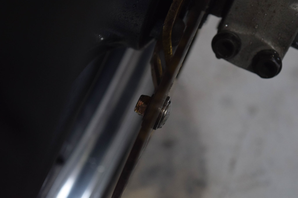
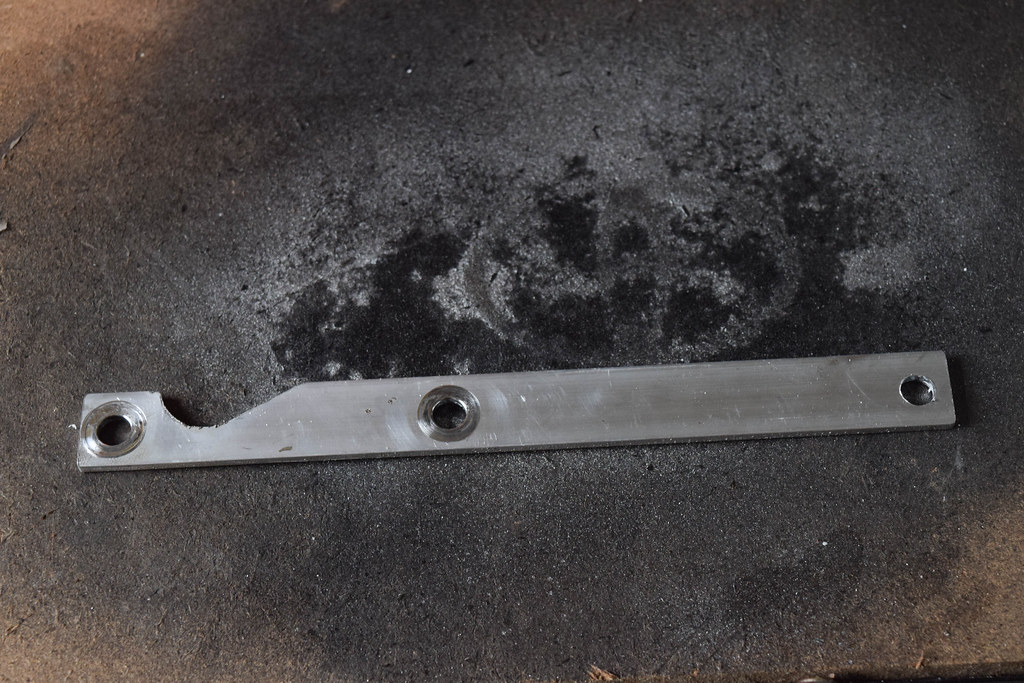
To mount the sensor a bracket cut from aluminium flatbar was made to fit infront of the left side caliper.
The sensor needs to be within 2mm or less from the sensor point to get the best performance.
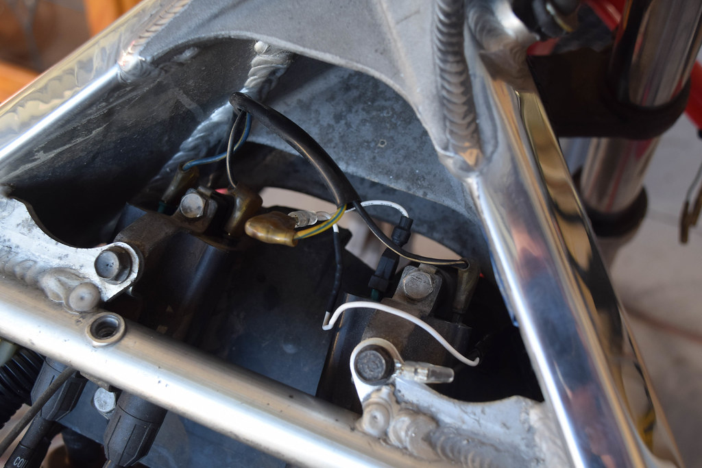
The last step of the installation before powering on the unit and configuring the settings was to cut the Orange/Blue wire from the CDI and splice it into the Black/White wire. This deactivates the speed limiter.
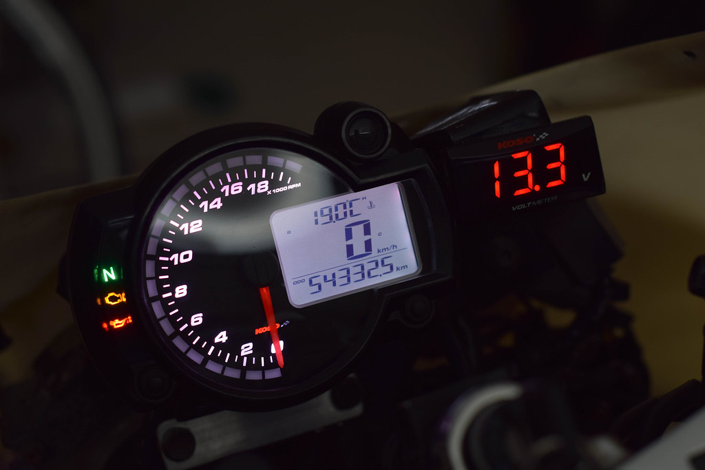
As a reference point for settings, 2 sensor points and 1810mm for the wheel circumference in the speed sensor setting and HiAct and 1 (4C-2P) in the RPM input pulse setting.
No comments:
Post a Comment